|
|
|
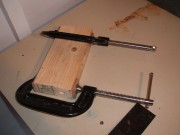
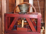
The Headstock shortly after being measured and cut, the two 'G' clamps help the glue to dry so hard that the two lenghts of wood are vertually inseparable.
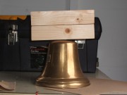
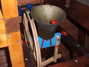
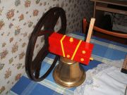
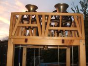
The bell is now mounted to its headstock, a cavity will be cut into the headstock in order for the bells 'Argent' to be fitted and bolted into place.
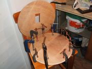
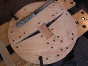
These plywood discs have been cut in order to make the wheel, three have to be made- two of the same size and one slightly smaller to be set in between the larger discs, this creates a groove in order for the rope to run through. One of the discs has a rectangular hole in the center in order for the headstock to be attached.
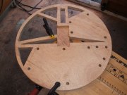
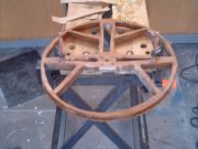
The wheel is now taking shape, large segments are cut out to form the spokes, half of this wheel is yet to be cut out, whats left of the more solid part will be cut out with a jigsaw.
The wheel is now fully cut, the rope groove is visible between the 'Shrouds' of the wheel, it has been fitted to the headstock in order to make sure its a perfect fit, the wheel will now be removed and varnished to a 'dark oak' finish. The 'Stay' is next to be made.
The stay has been cut, its length being from the lowest point of the headstock to the top of the wheel. Boltholes have been drilled out for the bolts in order to attach the stay to the headstock, the stay will be added to the opposite side of the headstock from the wheel.
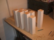
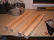
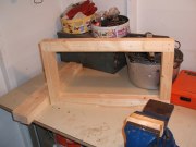
The short lenghts of wood above are the 'widths' and 'heights' of the frame, they have been undercoated for the blue top coat, thats why they are white.
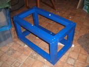
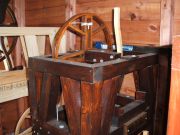
Now the frame has been assembled with screws and been under and top coated with 'Regal Blue' paint, the bell can now be lowered into place but the 'cross braces' have to be measured, cut, painted and installed.
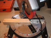
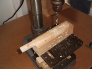
A 'cross brace' being measured and cut, the frame will have eight of these cross braces.
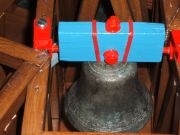
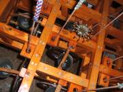
Although the frame above is different from the blue frame that has so far been used to show how a frame is built, it clearly shows the completed and installed cross braces along with the slider housing, the tiny red and yellow piece on the top, central part of the frame is the bearing cap.
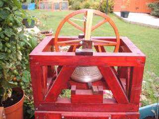
The picture above was taken from below the completed 'Britannic Bell', clearly visable below the bell is a thin, curved bar which runs the full length of the frame, this is called the 'Slider', named as so because it does just that- slides from one end of the 'Slider housing' to the other, the distance that which it slides is controlled by a block at each end of the slider running block. When the bell is being rung, the stay will coincide with the slider allowing the bell to set in its inverted or 'up' position, the next pull of the rope will swing the bell a full 360 degrees, then the stay will push the slider over to the other end of the sliders running block and rest against it, so the bell is inverted.
The image shown above left shows the 'Swiss Bell' in the inverted
or 'up' position, the stay rests against the pivoting
slider, without stay or slider the bell couldn't rest
as it does in this image. Careful examination of
this image and you just see the curved end of the
slider resting on its running block, the 'stop' at each
end of the running block prevents the slider sliding
too far which will cause the bell to swing right over
on itself.
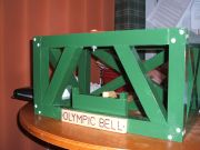
Olympic Bell in the raised position.
This image of 'Bergholt Doubles' tenor
shows the red gudgeons protruding
from each end of the headstock near
the bottom.
Early models like Swiss Bell above have their original wooden dowel gudgeons, nearly all the other models are either fitted with steel gudgeons when made or have had their wooden gudgeons replaced with the newer steel type.
Some models like Olympic Bell above have a clear stay and slider so that they are more visible against the often darker colour of the frame.
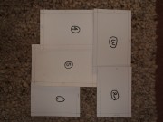
This white layout above is a cardboard template of how the frame of a Mini Ring will look, each individual bell pit is measured and a cardboard template is cut, once all the template pits are cut they are then fitted together to make a rectangular or square frame, in this instance there are five bells, with the bells hung in a anti-clockwise fashion. Once the template frame is the correct size, the real wooden frame can be built to the same dimensions as the cardboard frame. This template is for the Oakslider Doubles Mini Ring.
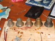
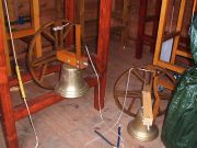
This picture shows five brass bells prior to hanging, these bells will become 'Bergholt Doubles', picture taken September 2007.
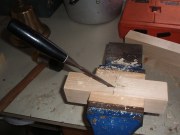
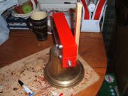
Part of the headstock for the Britannic Bell being made, a cavity is being chiseled out of the central part, this is for the bells 'argent' to fit into and then be secured by a bolt driven straight through the middle of the headstock.
|

HOW A MODEL IS MADE
It takes many hours to build a Church Bell model, whether it be a Mini Ring or a Single Bell model although Mini Rings take considerably longer to build than a frame which contains only one bell. The bell's wheel takes considerable time (around 40 hours) and a Mini Ring can contain up to ten wheels, depending on how many bells a model may contain. The parts of each model must be made in a particular order. That order goes as follows:
1.The 'Headstock' - a wooden beam from which the bell is suspended from, the length of the Headstock is normally the width of the bells 'Mouth' or 'Soundbow'- the part which is struck by the 'Clapper' during ringing.
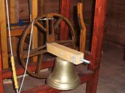
2.The 'Bell Wheel' - this is a plywood grooved wheel which is joined to one end of the Headstock, the wheel is normally around twice the height as the bell.
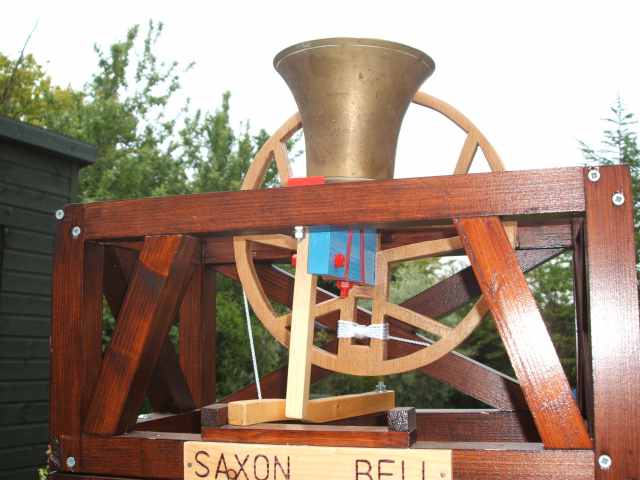
3.The 'Stay' - this is a wooden bar which is mounted onto the opposite side of the Headstock to the Wheel, its length being level with the height of the Wheel. The Stay is essential to enable the bell to be set in the upturned or 'up' position as it (the Stay) coincides with a wooden bar which is attached to the framework below the bell as shown in the image below:
This image of the 'Saxon Bell' shows how the 'Stay'- the wooden bar attached to the headstock rests against the 'Slider'- the horizotal wooden bar which sits below the bell in the framework, allowing the bell to rest in the 'upturned' position.
The stay has now been added to the headstock, once the wheel has been varnished that too will be screwed onto the stock at the opposite end. Once the wheel is added, the 'Gudgeons' have to be measured, cut and then fixed into place. As mentioned earlier the gudgeons are pivots to allow the bell to swing in its frame.
Now the wheel, stay and gudgeons are in their place, the wheel has now been varnished, the headstock has been painted and the nuts, bolts and gudgeons have been painted yellow to contrast with the red, oak brown and clear woodwork. The 'Cannon straps' are added next but these are purely a cosmetic feature that are simply added to create a more realistic look.
These four lengths of 44mmx44mm are the length beams for the frame, the height and width beams have to be cut but these will only be around half the size, in all twelve lengths of wood have to be cut to make the basic rectangle of the frame. Both of the beams that will make up the top part of the frame (where the bell will be suspended) have to have notches cut to act as 'bearings', one of the bottom lengths will have to have a hole drilled for the 'Sliders' bolt to be added.
This image below shows a close up
of one of the notches that will act
as bearing for the bell and its gudgeon,
the small hole to its right is for when
a cover or 'bearing cap' will be bolted-
this covers the gudgeon and its bearing
but can be swivelled open to allow the
whole bell assembly to lifted in and out
of the frame work for maintainance etc.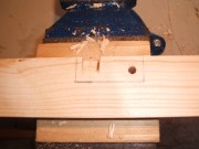
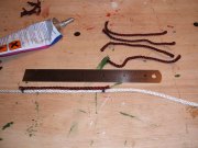
The above picture shows how a bell
rope is made, first a length of white
cord is measured and cut to the correct
length- the rope has to long enough
to span the circumference of the wheel
and have at least ten inches to spare.
The 'Sally' is made out of five or six
lengths of cord which can be of any
colour, the length of the sally is normally
determined by the height of the bell, a
six inch bell would have a six inch sally.
The lengths of 'sally' cord are then glued
around the main rope towards the bottom
end of the rope near the tail, once the
short lengths of cord are glued in place
they will completely encircle the six inch
length of the main rope. Once the rope has
been left to set a tail has to be made,
this is a small loop at the very end of the rope
several inches below the sally, depending on
the size of the bell. Small bells will only have
a sally of about four inches, larger bells would
have one up to ten inches. The rope is then
tied to the center of the upper most part of the
wheel.
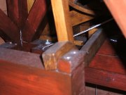
This picture is a close up of a bells
'stay' coinciding with the 'slider'
the slider is the curved wooden
bar which sits in the frame under-
neath the bell, the end part of the
stay can be seen resting against the
slider. With the next pull of the rope,
the bell will swing full circle and the stay
will push the slider over to the other end
of its running block and be stopped by the
'stops' which are at both ends of the running
block, then the stay will rest against the slider
like it is in this picture but at the opposite end
of the slider running block. This picture is of
the 'Titanic' Bell.
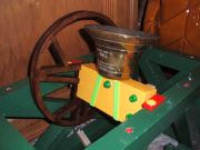
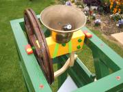
This is a picture of Brtannic bell with
completed bell gear, now the frame
has to be designed and built around it.
The top part of the frame has been
measured, cut and is having its bearings
marked out for the gudgeons to rest in
this part of the frame will now be dismantled
and have the bearings cut and the pilot holes
drilled for the screws and bolts.
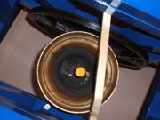
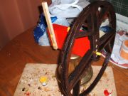
This picture is of a wheel belonging to the Tbilisi Bell, the
wheel is being improved which requires cutting, sanding and
re-varnishing in the places that have been cut. Once this
wheel is finished, it will then be fitted back onto the Tbilisii
Bells headstock.
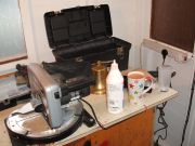
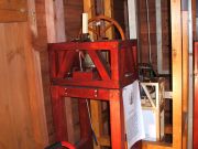
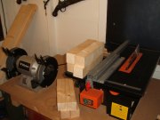
Some of the tools used along
with a cup of tea- very important!
the Britannic Bell is visible in front
of the tool box with the mitre saw
on the left- a very handy tool
for cutting wood-fast.
This image is of a bell wheel in its early
stages of construction, the small holes which
cover it are pilot holes for the blade of a
jigsaw to fit in order to cut the segments
of plywood out to form the spokes of the wheel.
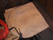
A wheel is made from a sheet of plywood,
three discs are cut out- two of the same
size and one slightly smaller. The picture
above is the cutting of one of the three discs-
the very beginning of making the wheel.
The differences between a curved or straight stay
As we can see from each of the models below the 'stay'- the bar of wood which is attached to the headstock on the opposite side to the wheel is sometimes either curved inwards or is completely straight. Curved stays are cut in a way so that the top of the stay is central to the headstock enabling the slider block to be set level in the frame below the bell. The center of balance with a curved stay means the slider block is not off-set with the bell as it is with a bell which has a straight stay.
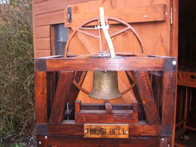
The Tbilisi Bell above has a curved stay, the slider block in the frame below is central to the bell. The top of the stay is central to the headstock meaning the point of balance is also central.
A straight stay which can be seen in the picture below is a completely staight bar of wood unlike a curved stay which is cut in order for the tip of the stay to be level with the centre of the headstock. Unlike a curved stay the tip of the straight bar of wood is off-centre with the headstock which means the centre of balance in conjunction with the slider and its rests is different with that of a curved stay, with a curved stay the slider block in the frame below is directly central with the bell and its headstock above, but with a staight stay the slider block is 'off to one side' or unlevel with its bell above, this is due to the tip of the stay being unlevel with center of the headstock. If a model such as the Number 33 Bell below which has a straight stay was fitted with a curved stay the centre of balance would be altered and the slider block below would be too unlevel for the bell to set 'up' properly. This problem would be similar to a curved stay model being altered with a straight stay- the central slider block would have to be altered in order for the bell to set 'up' properly.
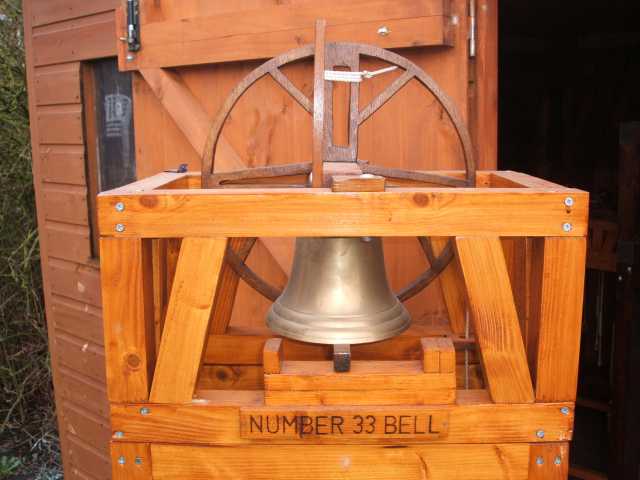
The Number 33 Bell above has a straight stay and the slider block can clearly be seen to be off centre or unlevel with the bell above as the tip of the stay is off centre with its headstock.
Lengths of wood which are part of a
frame being produced. Once sanded
they will then fitted together with other
longer lengths of wood after being varnished.
Number 33 and Abbey Bells are both
out of their frames, the gudgeons or
pivots can be seen protruding from the
ends of each headstock.
This image above of the Abbey Bell shows
one of its gudgeons (protruding out of the end
of the headstock in order to act as a pivot), this
gudgeon is a short length of threaded rod driven
about an inch into the headstock in order for the gudgeon
not to come loose or fall out- the entire bell assembly
would fall from its frame if one of the gudgeons failed.
|
4.The 'Gudgeons' - these are basically pivots in which enables the bell to swing in its bearings, one gudgeon is fitted at the central point at each end of the headstock and the entire bell assembly (bell, headstock and stay) is placed into bearings which are cut into the wooden framework, the bell can now swing freely in its frame. Grease is added to aid in smooth swinging.
5. The Framework- Now the 'Frame' or 'Bell Pit' has to be built. The bells frame has to be made to measure in order for the bell to be placed inside and be able to swing freely without the wheel, bell or stay brushing or banging against the framework. Width, height and length of the frame have to be calculated by measuring the dimensions of the headstock, gudgeons and wheel, if any of the frames dimensions are wrong (too high or too wide for example) the bell will not fit properly and/or the bell, wheel or stay will touch the sides of the frame as mentioned earlier, this we do not want.
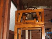 
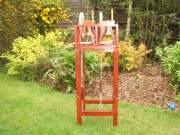
'Number 33' bell now hanging in its frame, the frame is just the right length, width and height for the bell, its wheel and headstock to rest and swing freely, also for the 'stay' to reach the 'slider' in the frame and not to touch the sides of the frame during ringing.
6. Cross- Braces- Once the frame is built and the bell fits and can swing properly, cross braces add an extra decorative touch, these are the same as 'struts' and give extra support to the frame, the angles have to be worked out and cut to length, at least eight cross braces need to be cut. Once these 'cross braces' have been cut they must be slotted into the frame to make sure a perfect fit is achieved and varnished afterwards- there's nothing worst than to spend half a day varnishing and then find out that whatever you've been making is too short or too long and has to be altered or even descarded- measure twice, cut once and only begin to varnish or paint when the said componant fits!.
7. The Slider- Now that the frame is complete with cross braces the 'Slider' now has to be measured and cut, this can be a bit of nuisance because you want a curved beam that can be moved on its running block by the stay and only the stay. A common problem while measuring the slider is that the bells soundbow (the flared, wider part) will catch the slider while only the stay must do this, a taller stay will touch the slider without the problem of the bell touching the slider as well, the key is to cut the stay that slightly bit longer during the early stages of production, even a couple of centermeters could make all the difference. Once the slider has been cut and its curved end is the right height and length and the stay coincides with it nicely, a running block now has be made along with a 'stop' at each end, this block has to be able to stop the slider from sliding too far or the stay could run over the top of the slider and the bell would swing right over on itself.
This is an image of a completed slider Another image of 'Saxon Bell', the stay can
housed inside its frame. coinciding with the slider, the next pull of the
rope will turn the bell 360 degrees and the stay
will push the slider along its running block and rest
against its 'stop'.
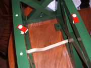
8. Rope Guides- With the slider completed and working properly- the stay must be able to rest against the slider without the bell coming into contact with the slider. A 'Rope Guide' now has to be made, a 'rope guide' is basically a small piece of wood with a hole drilled through it which is then glued on to the frame underneath the wheel, its use is to keep the rope level with the wheel during ringing, the rope would come out of the wheels groove if there was nothing to keep it level. Firstly, a plumb line is hung from the top of the wheel with plumb hanging down below the wheel, this creates a very straight line and replicates where the rope will hang, a piece of wood is measured and cut before hand and a mark is made on this small piece of wood from where the plumb line points, a hole of usually 13mm is drilled in to the rope guide or 'small piece of wood' and then checked to see if it will allow the rope to hang down in a straight line, once this has been achieved, the guide is then varnished and glued correctly into place- again with the aid of a good old fashioned plumb line.
The images above of Monks Minor (left) and Oakslider Doubles (right) are taken from below looking up at the framework, a couple of the rope guides are visible which keep the rope straight during ringing and stop it from coming out of the wheels groove. These rope guides have to be big enough for the ropes 'sally' to pass through as sometimes the bell assembly has to be lifted out of the framework, rope and all for repair or transporting the model.
9. Bearing Caps- With the bell assembly hanging in its frame, the gudgeons rest inside the bearings and take the weight of the bell and its headstock etc. The bearing and its gudgeon are exposed and visible so in order to create a more 'finished off' look wooden 'bearing caps' are made, these are of hard wood such as Oa, Ash or plywood- softwood is not used as the caps have a hole drilled through the center to secure them onto the frame with a bolt and softwood would spilt during the drilling process. The bearing caps need to swivel open allowing access to the gudgeon and its bearing and for the bell assembly to be lifted out of its frame for transportation etc. Bearing caps are varnished or painted a different colour to the framework and on some models the bolt which holds the cap onto the frame is also painted.
This birds-eye image of the Swiss Bell shows the
bearing caps which are coloured 'Dark Oak' compared
to the 'Red Mohogany' framework. The silver coloured
bolt is visible at one end of the cap and allows the cap
to swivel open to lift the entire bell assembly out of the frame.
10.Supporting Frame- Now that the Bearing Caps have been made and fitted, the Supporting Frame has to be made, this is basically a tall frame for the bell pit to sit on. With the bell pit on the ground, it would be impossible to attach a rope and ring it so it (the bell pit) has to be bolted onto a frame in order to raise it somewhat so a rope can be tied to the wheel and hang down below the bell. This 'Scaffold' is measured to the same width and length as the bell pit and once all the lengths of wood have been cut, sanded and varnished, they are then assembled with wood screws and the bell pit placed on top and then the two frames are joined together with bolts. The height of the supporting frame is determined by how long the rope is going to be- the rope has to be longer than the wheels circumferance with an extra eight or ten inches or so for the Sally and tail. The dimension of wood used for the scaffold is bigger than that of the bell pit as this adds stability and strength to the model and prevents it from moving to much from side to side during ringing, if for example a bells pit is made of 15mm x 15mm stripwood then its supporting frame will be of 32mm x 32mm softwood.
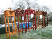 
These two examples above are of a bell pit sitting on its supporting frame, firstly the large five models sit on a frame of four feet with the rope hanging down below the bell making an overall height of around five feet four inches although the North Bucks Bell (not present in this picture) stands over six foot four inches tall. The second image is of the Crossroad Bells, the bell frame is of thin 15mm x 15mm stripwood and its supporting frame is of larger 32mm x 32mm softwood, if the supporting frames wood was of thin stripwood like the bell pit then it would be too tall for its height and would fall sideways during ringing.
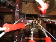
11.The Rope- The model is almost complete, now a rope has to be made. This is of white cord with coloured cord acting as the 'Sally', the length of the rope has to be greater than the circumferance of the wheel and have a bit to spare for the sally and tail end of the rope. To make the 'sally' (its length being around the height of the bell although sallys in Mini Rings are the same length) five or six pieces of coloured cord are cut, each being of the same length and then glued around the main rope near the bottom end to form a complete circle around a small section of the rope, once it has dried there should be a six inch coloured length of rope which encircles a small part of the main cord. There should be a short length of rope to spare at the very tail of the cord, a small loop is made with this extra length to create a looped tail- this should be at the very end of the rope and the sally should start a couple of inches from this tail. The top end of this cord is tied onto the upper central part of the wheel and fed through the rope guide in the frame below the wheel.
These images are of how a rope is made and tied onto the wheel, the left picture is of a sally being made- small strips of coloured cord are added onto the main white cord, in this case the sally is going to be purple in colour. The second image of White Wheel Doubles shows how the ropes are tied to the wheels, the rope passes through a 'fillet hole' in the 'sole' of the wheel and is tied to the central upper part of the wheel.
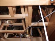
12.Rope Pulley- (Mini Rings only) In a church tower, the bells are sometimes left in the 'up' position after ringing, a bell and its rope is a potential hazzard when left in the 'up' position- people have been killed in the past when a bell has come off balance and crushed them to death if they are up amongst the bells or a person- normally a non ringer tugs on the rope of a raised bell and accidently pulls the bell off balance resulting sometimes in them being pulled 30ft off the ground and then falling back down to earth resulting in terrible injury or even death. To eliminate the rope hazzard some towers have a 'rope pulley' to hoist the ropes up high and out of harms way, this is basically a collection of hooks on the end of a rope which is lowered down from the ceiling and the tails of each bell rope then attached, the hooks are then pulled back up to the ceiling along with the bell ropes which keeps them up high and out of the way which makes them safe from people who might want to have a fiddle with them. The Mini Rings have a working rope pulley fitted but for only decorative use- their is no danger of being crushed by a bell weighing only a few ounces!.
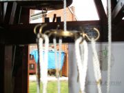
Just visible in this picture of Oakslider Doubles
is a rope pulley, below the frame a small bell can
just be seen attached to a cord, this small bell
has five hooks glued in place- for the ropes tails
to be hooked onto and be hoisted up high in the frame
this small hooked bell can be lowered from top to bottom
of the supporting frame with a cord. In this case a
bell has been used but in other cases such as Monks Minor
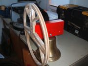
a small ships wheel with six hooks attached has been used to
hook the ropes onto. In a church tower in nearby Milton Keynes
a Second World War German soldiers helmet has been used to make
a rope pulley!.
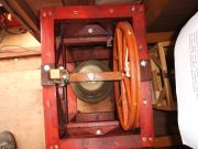
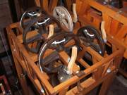
Another two examples of Rope Pulleys, above left taken at an unusual angle is the underneath of Caters Campanile, several rope guides are visible along with the rope pulley. In this instance the pulley is a small bell with ten hooks for the ten ropes. On the right is the rope pulley of Monks Minor, a ships wheel has had six hooks implanted into it, these hooks can be seen with the ropes loops attached to them.
13.Name Plate- With all the finishing touches complete, every model is given a name, so a small name plate is made from softwood. This plate is varnished differently from the main framework, firstly a stencil is used to neatly make out the lettering and then the letters are filled in with black ink, as the plate is glued and nailed onto the frame, two pilot holes are drilled at each end of the name plate. Once the plate is varnished then it is glued and tacked (nailed) into place onto the side of the frame below the slider running block.
The Saxon Bell proudly displays its name plate, all of the models have these wooden plaques to identify them, though not all are coloured clear like the example above. The plates are positioned on the framework below the slider running block and are glued and nailed into place.
The model is now complete and can now be displayed and demonstrated with pride, weeks of work has finally paid off and these models will last a lifetime.
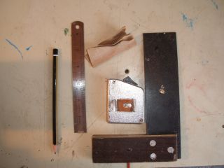
The most commonly used tools in model making
a pencil, steel ruler, set squire, tape measure and sandpaper.
|